Air Ride Switch Wiring Diagram

Vt Commodore Ignition Wiring Diagram, Complete Wiring Diagrams For Holden Commodore VT, VX, VY, VZ, VE, VF, 5.36 MB, 03:54, 32,796, John Amahle, 2018-08-01T19:37:41.000000Z, 19, Vt Commodore Ignition Wiring Diagram, to-ja-to-ty-to-my-to-nasz-swiat.blogspot.com, 1272 x 1800, jpeg, bcm pcm 12j swiat nasz, 20, vt-commodore-ignition-wiring-diagram, Anime Arts
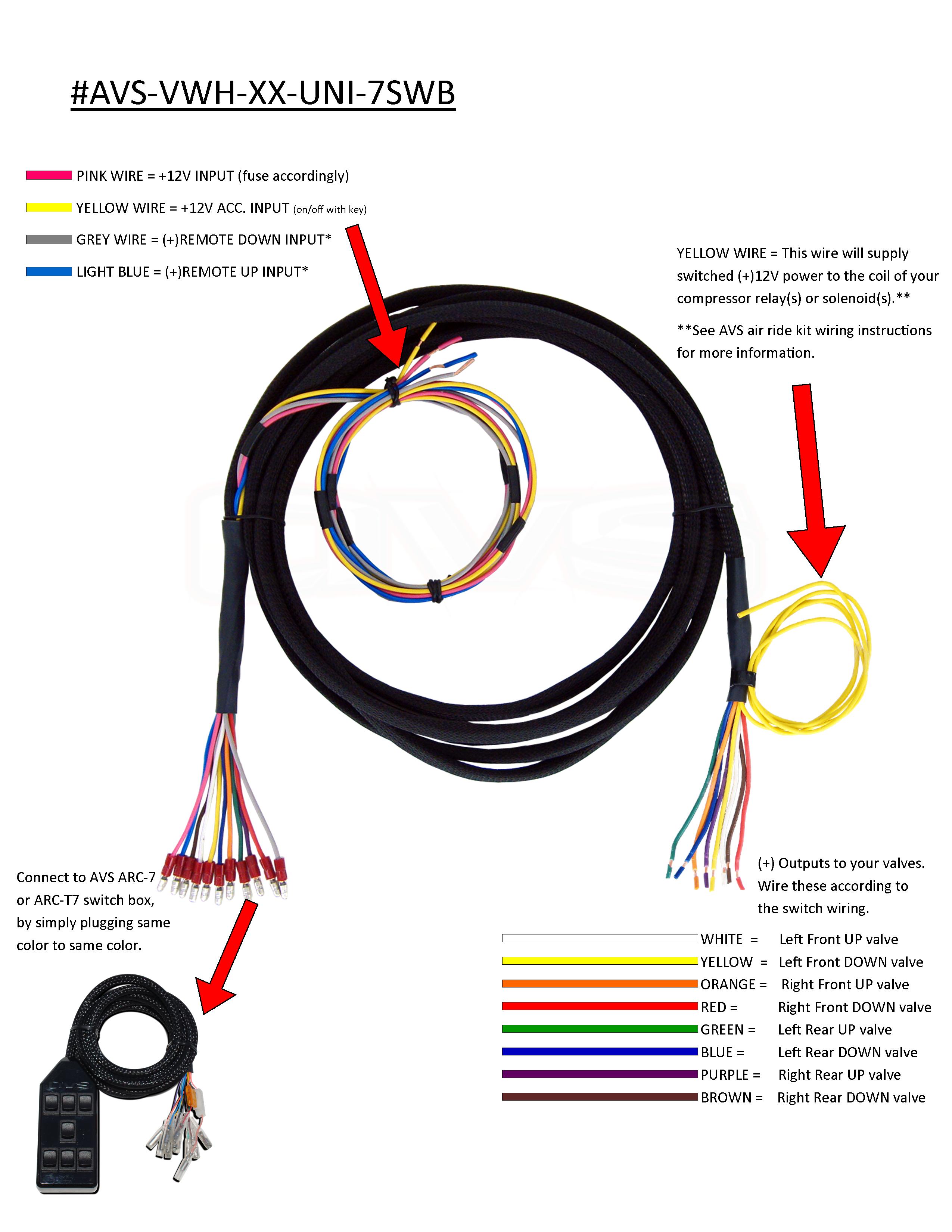
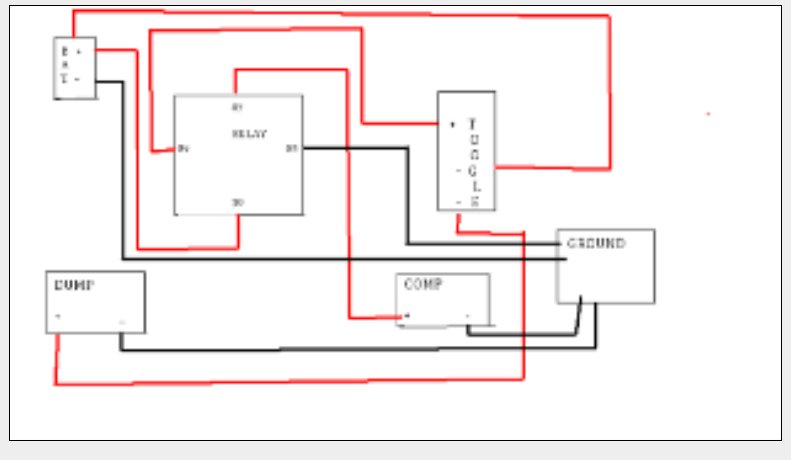
Use included fuse within 18” of battery. Connect levelpro sensors see levelpro section for more information on installing and calibrating height sensors. (see page 8) connect display / controls: How to wire up a single compressor, multiple compressors to both relay and solenoid.
Connect the red wire (pin 2) to constant +12v. Connect the yellow (pin 4) to the compressor (less than 40amp) or compressor relay (over 40amp draw). 1. this output is only designed to supply power to a compressor that requires less than 40 amps. Air ride pressure switch wiring diagram from www. untpikapps. com. Print the electrical wiring diagram off plus use highlighters to trace the routine. When you employ your finger or perhaps the actual circuit along with your eyes, it may be easy to mistrace the circuit. One trick that i use is to print out the same wiring plan off twice. Toggle switch waterproof boot $4. 99. View all dirty air parts;
Wiring, Switch Box Cleaver Air Ride Switch, Wiring Diagram 4 Valve, Airbag Suspension Arresting

Pin on baged

Air Ride Switch Wiring - Street Source

Air Ride Switch Box Wiring Diagram
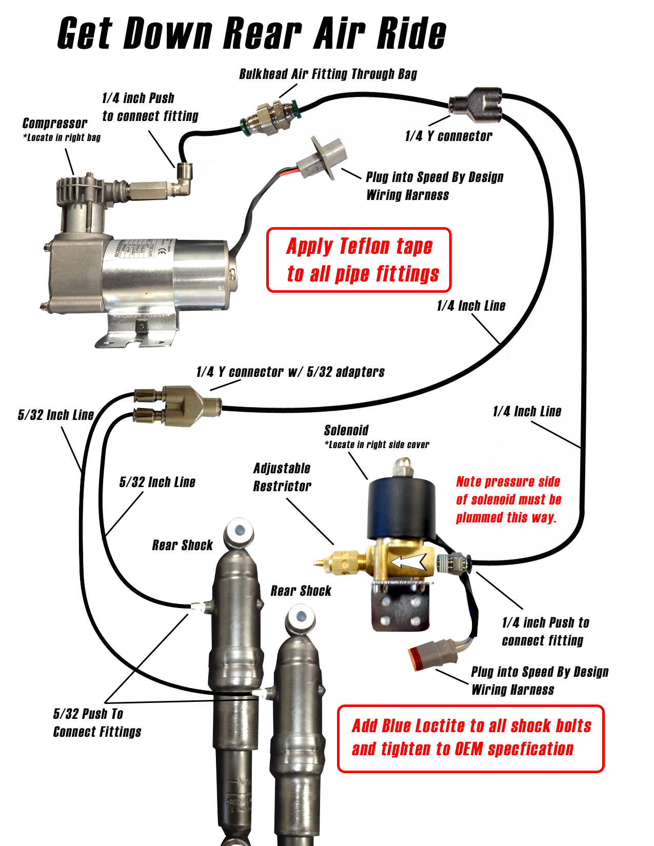
Rear - Get Down Air Ride - $529.00 - Speed By Design
DIY Air ride wiring help?? - Harley Davidson Forums
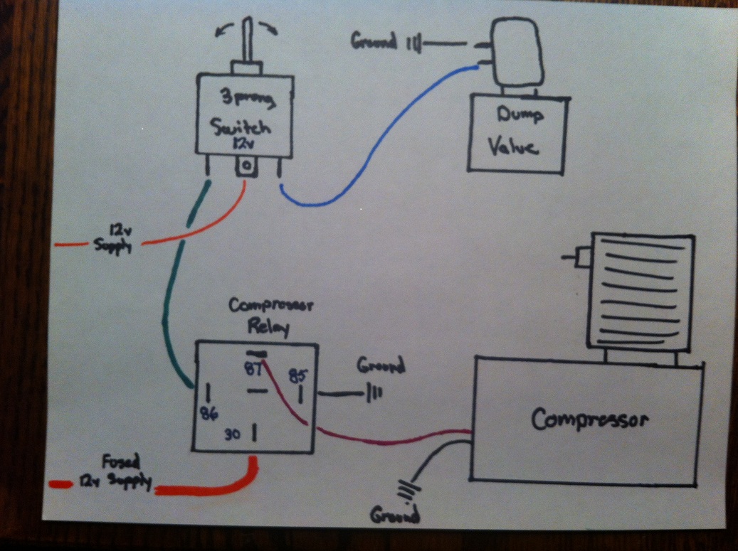
Air Ride Suspension Control - Hackster.io
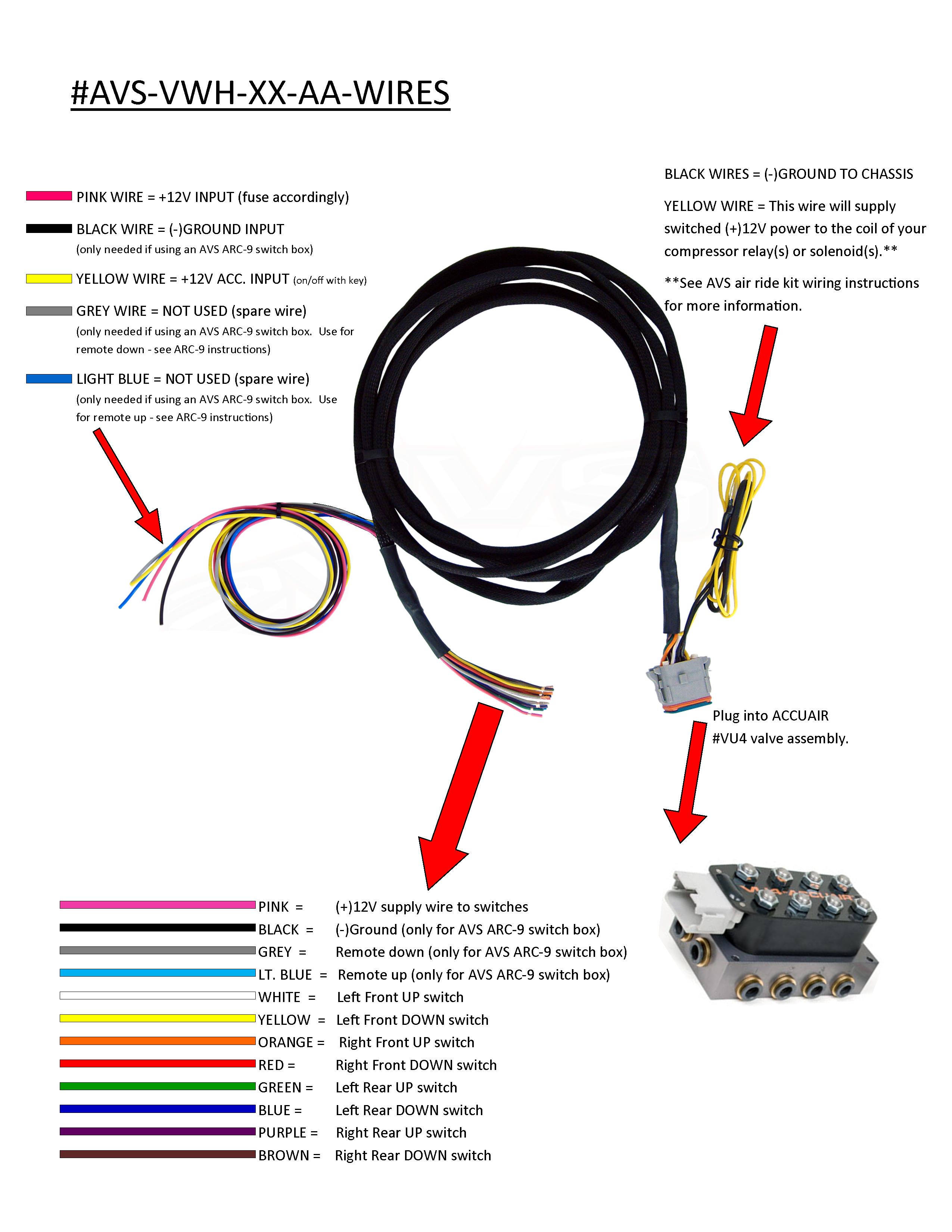
Few questions about my air ride management.
Arnott air ride wiring... - Harley Davidson Forums
Evolve Dual Compressor Wiring Kit by AVS - Complete Air Ride


0 Response to "Air Ride Switch Wiring Diagram"
Post a Comment