Asco 24vdc Solenoid Valve Wiring Diagram
Vt Commodore Ignition Wiring Diagram, Complete Wiring Diagrams For Holden Commodore VT, VX, VY, VZ, VE, VF, 5.36 MB, 03:54, 32,796, John Amahle, 2018-08-01T19:37:41.000000Z, 19, Vt Commodore Ignition Wiring Diagram, to-ja-to-ty-to-my-to-nasz-swiat.blogspot.com, 1272 x 1800, jpeg, bcm pcm 12j swiat nasz, 20, vt-commodore-ignition-wiring-diagram, Anime Arts
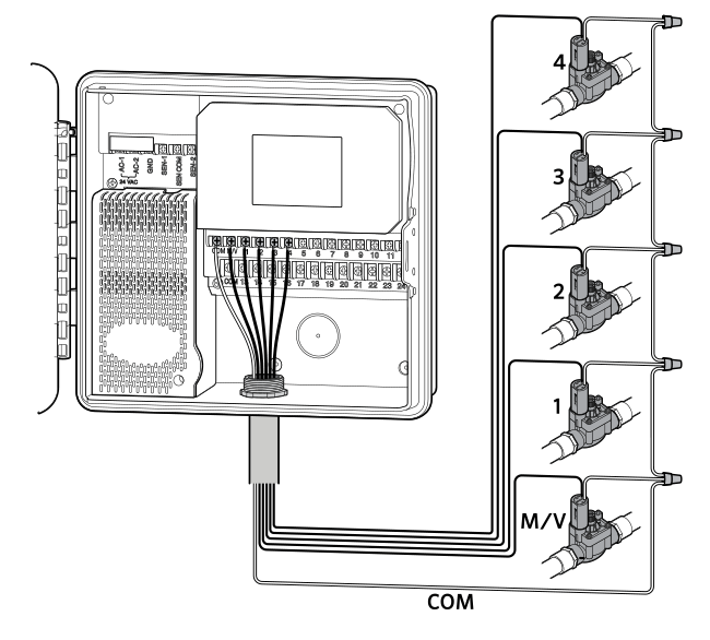
Through the valve when the coil is energized. Two types of constructions apply: Direct acting when the solenoid is energized, the core directly opens the orifice of a normally closed valve or closes the orifice in a normally open valve. Wiring of the solenoid valve is simple.
In terms of ac, the anode and cathode cannot be left unconsidered when wiring the solenoid valve. In terms of dc, attention should be paid to anode and cathode, and that the voltage should be. Ƒ m safety shutoff valve; L general purpose valve. Refer to engineering section (approvals) for details. ≈ valves not available with explosionproof enclosures. ∆ on 50 hertz service, the watt rating for the 6. 1/f solenoid is 8. 1 watts. « ac construction also has pa seating. Asco redhat ii solenoids and coils the typical watt ratings given show the relationship between different classes of coil insulation and the watt ratings to achieve higher temperature capabilites.
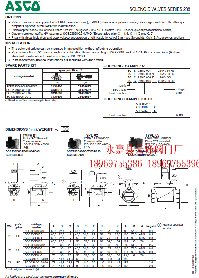
Asco Solenoid Valve Wiring Diagram - Free Wiring Diagram
biopsia project
Asco solenoid Valve Wiring Diagram Gallery - Wiring Diagram Sample

Solenoid Valve Wiring Diagram - Complete Wiring Schemas

78679939 dvc6000manualinstrucciones
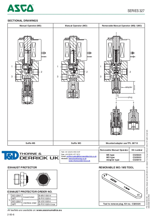
Asco solenoid Valve Wiring Diagram Gallery - Wiring Diagram Sample

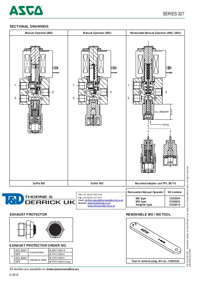
Asco Solenoid Valve Wiring Diagram - Free Wiring Diagram

Asco solenoid Valve Wiring Diagram | Free Wiring Diagram

32 Asco Redhat 2 Wiring Diagram - Wiring Diagram Database

Asco solenoid Valve Wiring Diagram Collection | Wiring Collection


0 Response to "Asco 24vdc Solenoid Valve Wiring Diagram"
Post a Comment