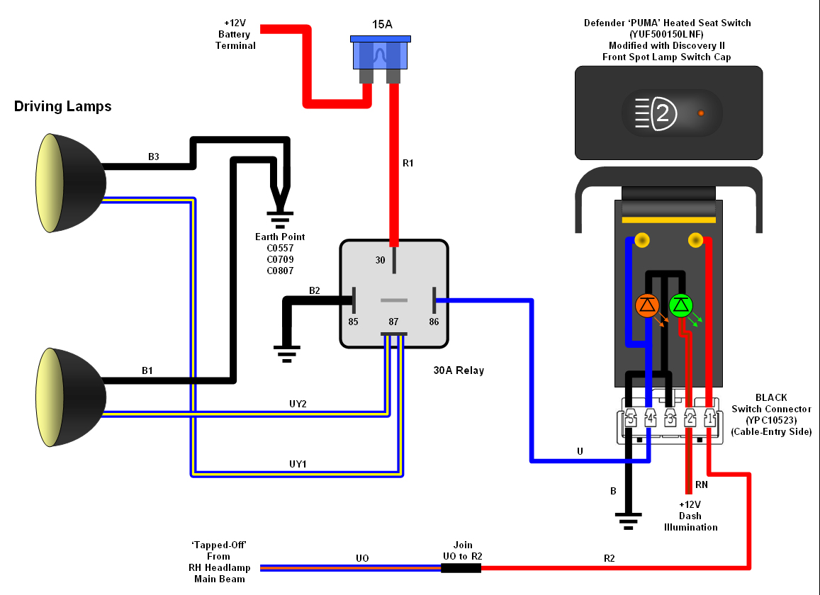
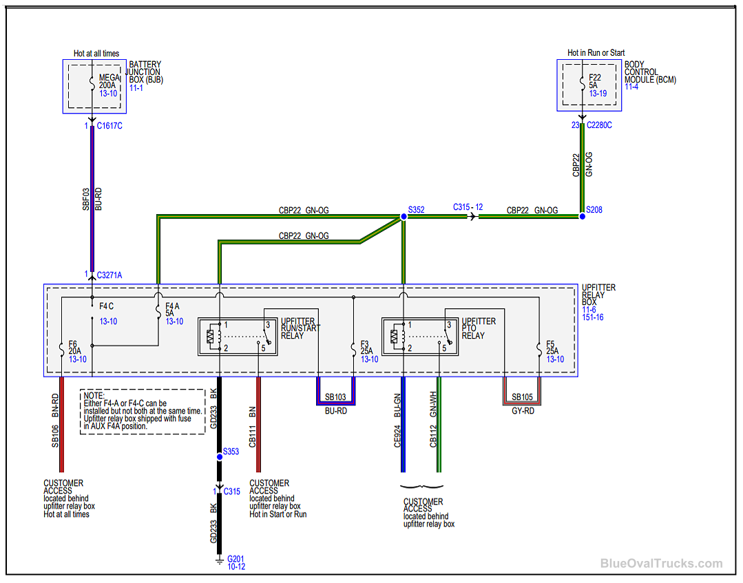
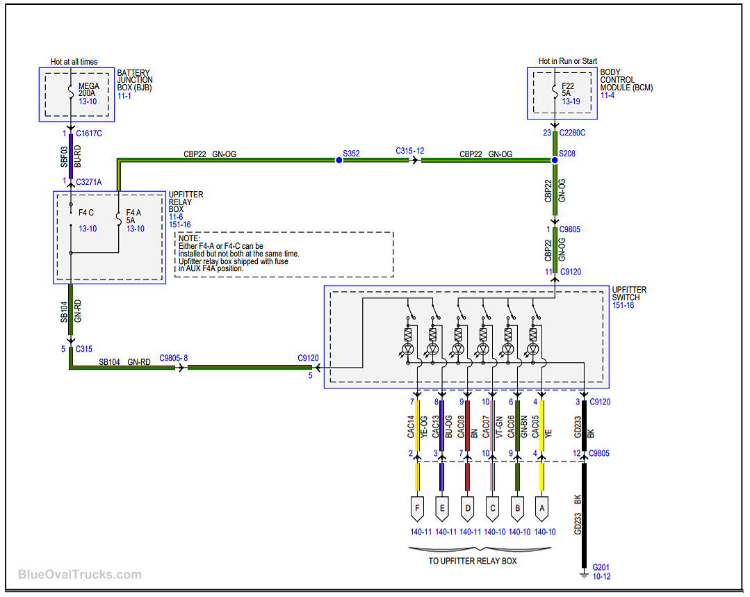
Auxiliary Switch Wiring Diagram

Vt Commodore Ignition Wiring Diagram, Complete Wiring Diagrams For Holden Commodore VT, VX, VY, VZ, VE, VF, 5.36 MB, 03:54, 32,796, John Amahle, 2018-08-01T19:37:41.000000Z, 19, Vt Commodore Ignition Wiring Diagram, to-ja-to-ty-to-my-to-nasz-swiat.blogspot.com, 1272 x 1800, jpeg, bcm pcm 12j swiat nasz, 20, vt-commodore-ignition-wiring-diagram, Anime Arts
The black wire going to the load will always connect to the common screw on the 2nd switch in the circuit. Then the traveler wires are connecting both. Connecting auxiliary switch harness ( 1:01) using the diode dynamics oem auxiliary switch harness, connect to your power wire. Using wire strippers, remove enough insulation to make a good connection.
The aux switch bank is standard on wildtrak, first edition, badlands, and black diamond broncos and an option on base, big bend, and outer banks. I thought i would create a how to guide for others wanting to add auxiliary lighting, etc to their atvs with some pictures of my latest setup. 1x 40a relay 1x 20a switch 4x 10a switch assorted quick disconnect connectors for switch pins (blue + red) eye lit connectors for battery connections 10 gauge wire (black + white) In the first step, the power comes to the switch and then travels to the light. For this configuration, you will have to work with the three wires mentioned above. Strip off the wire’s sheath approximately 6 inches, and then you will see the black, green, and white wire. Also, peel black and white wire for about ¾ inch. Ford auxiliary switch wiring diagram. Ford auxiliary switch wiring diagram from faroutride. com.
Wiring auxiliary lights to independent switch | DiscoWeb

My Knight Rider 2000 project: Parking and Headlights Lower Console Auxiliary Switch Wiring

My Knight Rider 2000 project: Parking and Headlights Lower Console Auxiliary Switch Wiring

2012 Dodge Auxiliary Switches Wiring Diagram

Aux Light Wiring Diagram 5 Wire Relay | Wiring diagram, Electrical wiring diagram, Trailer light

2017 And Newer Ford Super Duty AUX Upfitter Switches – Blue Oval Trucks

aux light relay wiring question.... - Stromtrooper Forum : Suzuki V-Strom Motorcycle Forums

2017 And Newer Ford Super Duty AUX Upfitter Switches – Blue Oval Trucks

Wiring Diagram For Auxiliary Reverse Lights

Auxiliary Reverse Lights Wiring Diagram For - diagram definition


0 Response to "Auxiliary Switch Wiring Diagram"
Post a Comment