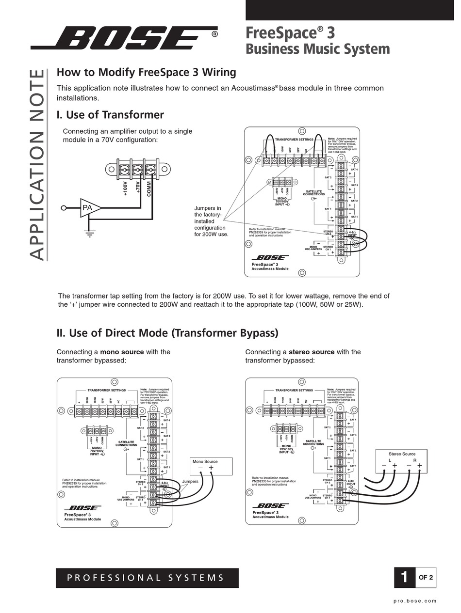
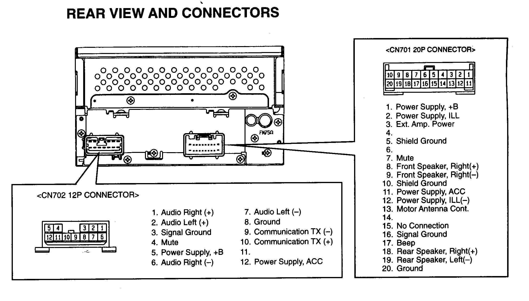
Bose Acoustimass 3 Series Iii Wiring Diagram
Vt Commodore Ignition Wiring Diagram, Complete Wiring Diagrams For Holden Commodore VT, VX, VY, VZ, VE, VF, 5.36 MB, 03:54, 32,796, John Amahle, 2018-08-01T19:37:41.000000Z, 19, Vt Commodore Ignition Wiring Diagram, to-ja-to-ty-to-my-to-nasz-swiat.blogspot.com, 1272 x 1800, jpeg, bcm pcm 12j swiat nasz, 20, vt-commodore-ignition-wiring-diagram, Anime Arts
To place them more than 30 fæt (9. 2 m) apart, you will need heavier gauge wlre. In case there’s a surface wire, it will be a water piping wire held in place by a attach on the same side since the fairly neutral terminal. The actual distinction between the wires will allow you to wire your home properly and avoid the high voltage of swapping the neutral and hot. Speaker arrays to direct the sound to the front and back of the listener (see figure 3).
Powered acoustimass module bose ® acoustimass speaker technology takes advantage of the fact that the source. It reveals the components of the circuit as simplified forms and also the power and also signal connections between the gadgets. We appreciate your choice of the bose acoustimass 6 series iii or acoustimass 10. Bose acoustimass 10 wiring diagram unique delighted bose lifestyle 5. Assortment of bose acoustimass 10 wiring diagram. What the carton contains. Placement of the acoustimass bass module. Connect the bass module. The bose rep should have told you this.
Checking your connections, Setting up your acoustimass, 3 speaker system | Bose Acoustimass 3
54 Bose Acoustimass 3 Series Iii Wiring Diagram - Wiring Diagram Plan

54 Bose Acoustimass 3 Series Iii Wiring Diagram - Wiring Diagram Plan

Bose Acoustimass 7 Wiring Diagram

Download free pdf for Bose Acoustimass 10 Series III Speaker System manual
Bose Black Acoustimass Wiring Diagram

5.1 through only 2 channels ? | Audiokarma Home Audio Stereo Discussion Forums

[DIAGRAM] Bose Acoustimass Speaker Wire Diagram FULL Version HD Quality Wire Diagram
![Bose Acoustimass 3 Series Iii Wiring Diagram [DIAGRAM] Bose Acoustimass Speaker Wire Diagram FULL Version HD Quality Wire Diagram](https://schematron.org/image/bose-acoustimass-10-iii-wiring-diagram-5.png)

0 Response to "Bose Acoustimass 3 Series Iii Wiring Diagram"
Post a Comment