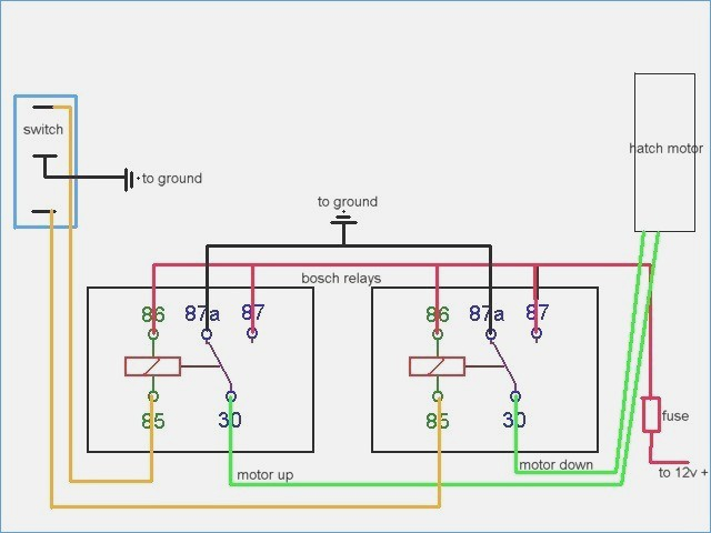
Bremas Switch Wiring Diagram

Vt Commodore Ignition Wiring Diagram, Complete Wiring Diagrams For Holden Commodore VT, VX, VY, VZ, VE, VF, 5.36 MB, 03:54, 32,796, John Amahle, 2018-08-01T19:37:41.000000Z, 19, Vt Commodore Ignition Wiring Diagram, to-ja-to-ty-to-my-to-nasz-swiat.blogspot.com, 1272 x 1800, jpeg, bcm pcm 12j swiat nasz, 20, vt-commodore-ignition-wiring-diagram, Anime Arts
Bremas offers 4 series of cam switches: Cr series from 12 to 40a, 690v rated insulation voltage, ip20 terminals protection degree, ip65 handles protection degree. Ca series from 12 to 630a, 690v rated insulation voltage, ip00 terminals protection degree, up to ip65 handles protection degree. Cq series from 12 to 32a, 690v rated insulation.
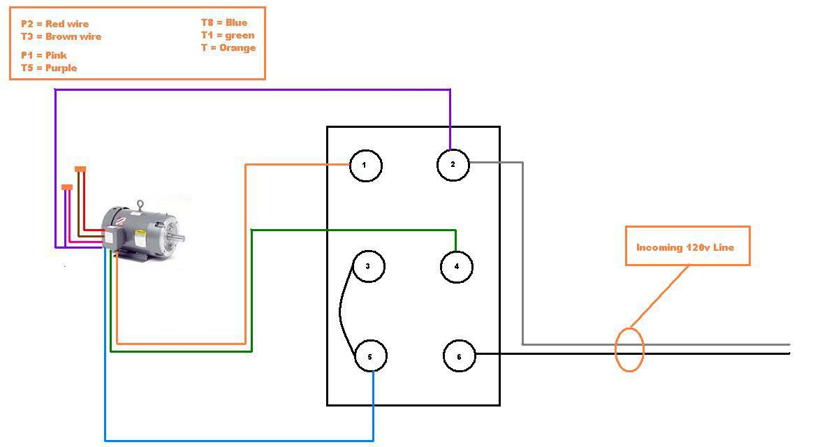
Clicks into the up or down position. Bremas boat lift switch wiring diagram the following procedure is for wiring the already wired drum switch* to the motor using 14/5 bremas # cys2r, bremas # cys2r, furnas. Wiring a combo switch : Available diagrams for every application: Leeson boat lift wire controller trying am orange. Ul, nema, ce, sa compliant. Bremas switch wiring diagram. With over 50 years of experience, bremas is a specialist in the industrial sector for standard and custom products. A wiring diagram is a type of schematic which uses abstract photographic icons to show all the affiliations of components in a system.
Bremas Boat Lift Switch Wiring Diagram Sample

I am hooking up s Bremas switch to a new boat lift motor and need help wiring it, No tester I

1E1F58 Bremas Drum Switch Wiring Diagram | Ebook Databases
I have a GH-A Bremas switch for a boat lift. the motor is a Westinghouse series EA81 3/4 hp code

Bremas Series A1700 Wiring Diagram

Bremas Series A1700 Wiring Diagram

Bremas Series A1700 Wiring Diagram

Bremas Series A1700 Wiring Diagram
Bremas Boat Lift Switch Wiring Diagram Gallery | Wiring Diagram Sample

Bremas Switch Wiring Diagram - Wiring Diagram


0 Response to "Bremas Switch Wiring Diagram"
Post a Comment