Cap Start Cap Run Wiring Diagram
Vt Commodore Ignition Wiring Diagram, Complete Wiring Diagrams For Holden Commodore VT, VX, VY, VZ, VE, VF, 5.36 MB, 03:54, 32,796, John Amahle, 2018-08-01T19:37:41.000000Z, 19, Vt Commodore Ignition Wiring Diagram, to-ja-to-ty-to-my-to-nasz-swiat.blogspot.com, 1272 x 1800, jpeg, bcm pcm 12j swiat nasz, 20, vt-commodore-ignition-wiring-diagram, Anime Arts
Motor run capacitor wiring diagram wiring diagram from annawiringdiagram. com. Split phase single value capacitor electric motor (dual voltage type). What does a capacitor do. Single phase motor capacitor connection electric motors weg standard product catalog w22 cmrw series capacitors for w21 tefc cast iron farm duty 10 hp 4p 215t 1ph 230 v 60.
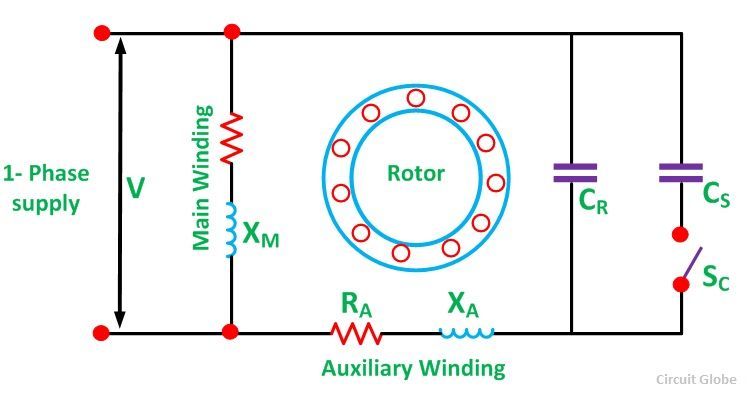
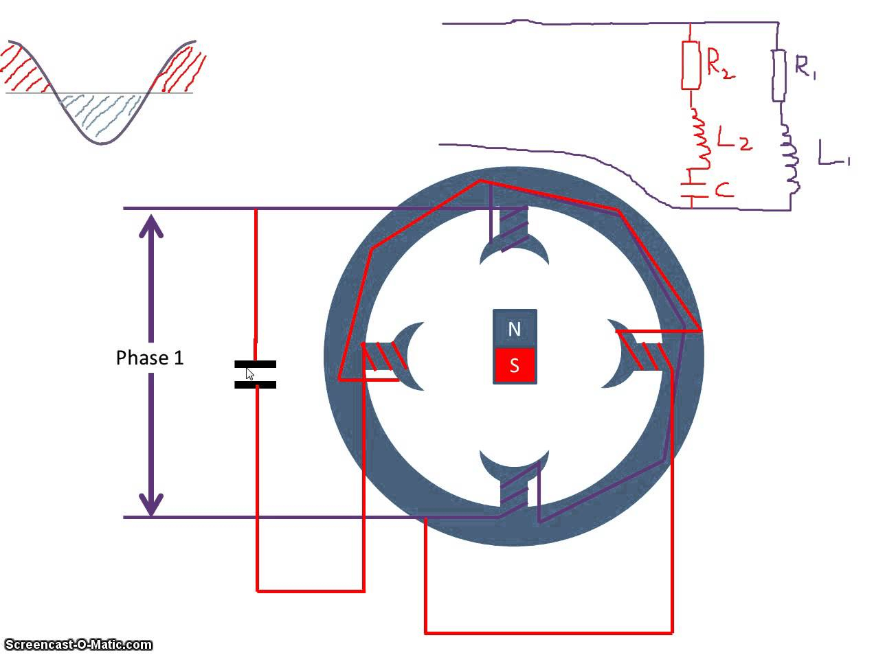
You will find out how to identify to main and auxilliary winding and change motor rotation. start capacitor, ru. Terminal r5 should be l2/neutral, r4 should be l1/hot, terminal r1 should be through your start capacitor and r2 should be through your run capacitor. They are compressor specific due to current draw. Current flows to the start leg through the start relay. That current heats up a thermoswitch inside the relay that opens to drop the start winding. There, s stands for a start wire connector, r stands for run wire connector and c stands for the common connector. The starting or auxiliary winding and the main or running winding. The two windings are displaced by an angle of 90° in the space. This motor uses two.
Fig.13 capacitor start capacitor run motor wiring diagram | Electrical A2Z
What is a Capacitor Start Capacitor Run Motor? - its Phasor Diagram & Characteristics - Circuit

Capacitor Start Capacitor Run Motor Wiring Diagram | Wiring Diagram

Capacitor start capacitor run motor circuit (wiring) diagram and torque-speed curve | Electrical

Autosportswiring: Capacitor Start Capacitor Run Motor Wiring Diagram

Start Capacitor Wiring Diagram In Starting | Electrical wiring diagram, Compressor, Electrical

Capacitor Start Capacitor Run Motor Wiring Diagram - Cadician's Blog

Motor Starting Capacitor Wiring Diagram

Speedaire Compressor Start Capacitor Wiring Diagram For And Run | Wiring Diagram Database

Single Phase Capacitor Start Capacitor Run Motor Wiring Diagram | Electrical circuit diagram, Ac


0 Response to "Cap Start Cap Run Wiring Diagram"
Post a Comment