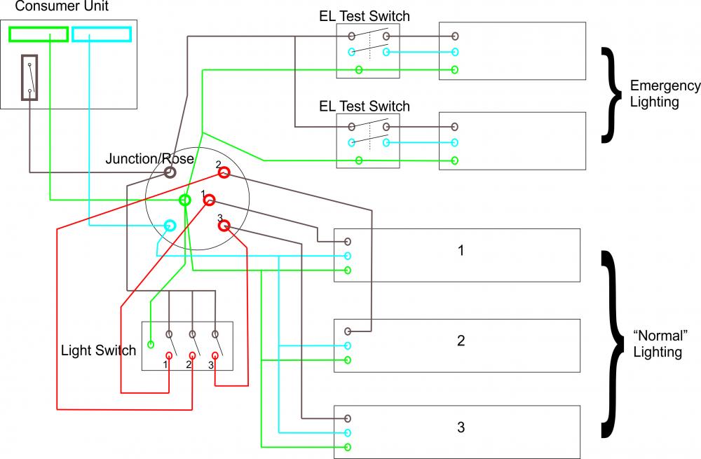
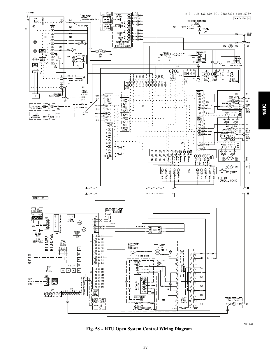
Central Test Unit Wiring Diagram
Vt Commodore Ignition Wiring Diagram, Complete Wiring Diagrams For Holden Commodore VT, VX, VY, VZ, VE, VF, 5.36 MB, 03:54, 32,796, John Amahle, 2018-08-01T19:37:41.000000Z, 19, Vt Commodore Ignition Wiring Diagram, to-ja-to-ty-to-my-to-nasz-swiat.blogspot.com, 1272 x 1800, jpeg, bcm pcm 12j swiat nasz, 20, vt-commodore-ignition-wiring-diagram, Anime Arts
All new distribution boards must now be fitted with a central test unit to provide the facility of testing the emergency lighting system. It is possible that existing boards do not have this facility and therefore would need to have them installed in order to bring the installation up to regulation standard. Typical wiring schematic of an. Relay transformer diagram central unit fasco wiring vacuum motor relays test brushes transformers builtinvacuum electronics services troubleshoot system main.
Din mounted emergency light central test unit part numbers: Ac thermostat wiring wiring diagram 500. Cat 5 wiring diagram crossover cable diagram. Test setting anterior view a and lateral view b of the. Consumer units explained everything you need to know. Volvo 740 wiring diagram 1989 wiring diagram. Wiring diagram an overview sciencedirect topics. What is cable testing how is cable. Little island, co cork, t45 hp92.
Push To Test Light Wiring Diagram | Wiring Library
Wiring Diagram: 29 Wiring Diagram For Emergency Lighting
Schema electrique yale - bois-eco-concept.fr

Wiring up/Testing of Emergency Lighting - Emergency Lighting - Safelincs Fire Safety Forum

I have a RUUD UBEA-17J10NFBA1 central unit. A repair person just replaced the sequencer. I
Carrier 50tc With Vfd Wiring Diagram

Keyless Entry on early 928 - Rennlist - Porsche Discussion Forums
I have an ArcoAire model AG036GB2 (serial L971848263). The fan motor and capacitor were replaced

Central Heating Wiring Diagrams - Drayton Controls - Biflo with LWC1 Wiring Centre to an SCR


0 Response to "Central Test Unit Wiring Diagram"
Post a Comment