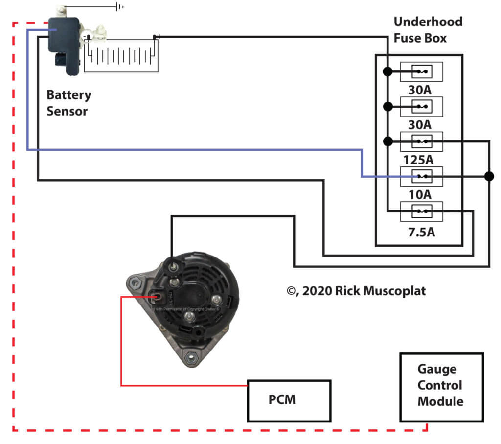
Charging Alternator Wiring Diagram

Vt Commodore Ignition Wiring Diagram, Complete Wiring Diagrams For Holden Commodore VT, VX, VY, VZ, VE, VF, 5.36 MB, 03:54, 32,796, John Amahle, 2018-08-01T19:37:41.000000Z, 19, Vt Commodore Ignition Wiring Diagram, to-ja-to-ty-to-my-to-nasz-swiat.blogspot.com, 1272 x 1800, jpeg, bcm pcm 12j swiat nasz, 20, vt-commodore-ignition-wiring-diagram, Anime Arts
All of these cars have a 3g series alternator. Same voltage as the alternator. If the relay (must have a nc contact) and the lamp are connected as shown in fig. 2 the lamp will go out when the alternator is charging the batteries.
(fig 2) balmar alternator wiring with indication lamp Both of the extra ports on the regulator are unnecessary. Charging system handles all of the vehicle’s electrical requirements. Charging system the alternator supplies power for the vehicle when the engine is running and engine speed is above idle. Car not charging diagram help pelican parts forums vw generator alternator wiring guide power equipment engine systems and dc circuits wilbo666 toyota alternators hyundai elantra schematic diagrams system frequently asked questions faq ls conversion question the 1947 present chevrolet gmc truck message board network catalog how to install a diode. Da plug connects to the coil + terminal through the ballast resistor if there is one. Charge wire connects from the alternator to the battery through the the resistor or directly to the key switch itself (switched side). This wiring configuration will excite the alternator to start charging when the engine is running at low rpm’s. If you are having trouble hooking the alternator up i just uploaded a video explaining how to do it, sorry i got a little ahead of myself in this videoif car.
New Wiring Diagram Car Charging System #diagram #diagramtemplate #diagramsample | Alternator

Honda alternator and charging systems explained — Ricks Free Auto Repair Advice Ricks Free Auto

Wiring Diagram for charging system - RX7Club.com
CHARGING SYSTEM ALTERNATOR in 2021 | Alternator, Diagram, Free energy generator

Charging System Upgrade with a Tuff Stuff Alternator - Hot Rod Network

Alternator System Wiring Diagram - Wiring Diagram Networks

Charging System Wiring | For A Bodies Only Mopar Forum
Cucv Alternator Wiring Diagram

Wiring Diagram Alternator Warning Light


0 Response to "Charging Alternator Wiring Diagram"
Post a Comment